QUICKSURFACE Full
Scan to CAD software for transforming 3D scan meshes from any 3D scanner into CAD models. Equipped with simple yet powerful features you can quickly convert your digitised data into ready to use models. Explore some of the main features.
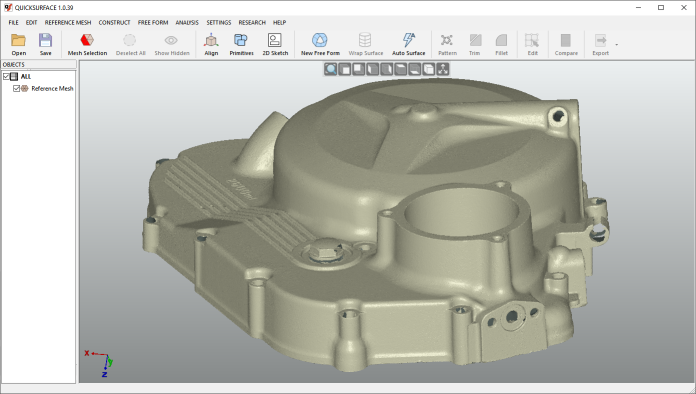
Scan Data Import
Load data from any scanner using the industry standard STL, OB or PLY mesh files. For long range scanners, the data can be imported using PTX file format. Being a 64 bit application allows the user to load any size mesh. For the purposes of manipulation the build-in polygon reduction function allows the user to create a mesh with suitable number of triangles without compromising the quality of the mesh.
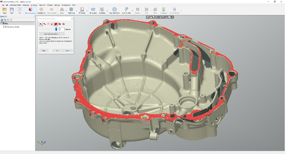
Interactive selection
Simple to use tools to quickly extract areas of interest. Magic wand, brush and free form selection allows the user to identify the areas that represent features or free form surfaces
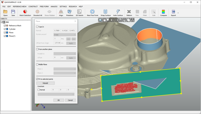
Primitives extraction
Reconstruct quickly planes, cylinders, cones and spheres. Create relations between them as peprendicularity, parallelism and coincidence.
You can also create a reference geometries like lines and points for use in align mesh to space operation for correctly positioning the object into the world coordinate system
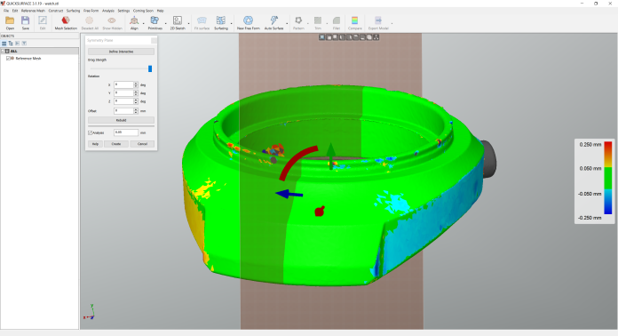
Symmetry Plane
Find a plane of symmetry of the object. Use the analyser to identify the quality of the position of the plane. Fine tune the position with on-screen controls to achieve the best results.
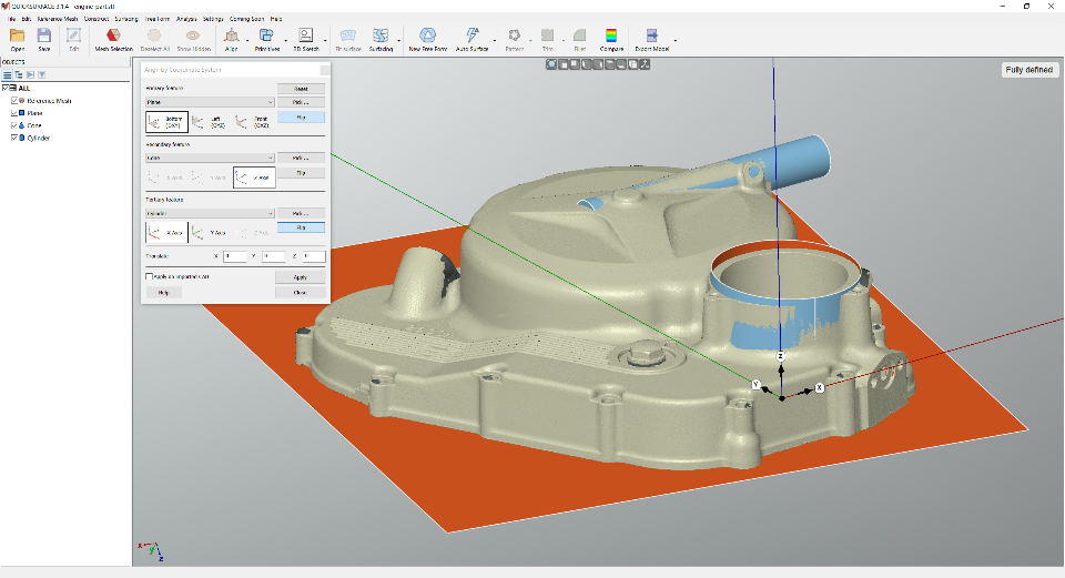
Object align
Position the object into the world coordinate system using the extracted primitives. The interactive definition of the coordinate system allows the user to adjust the correct orientation of the object.
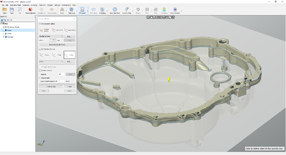
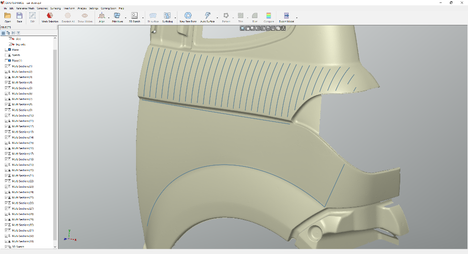
2D Sectioning
Interactive sectioning allows the user to extract reference points for 2D Sketching. Align the section plane to extracted primitives, CAD faces and even create section interactively on the screen. For the purposes of lofting – the user can also create multiple sections at once
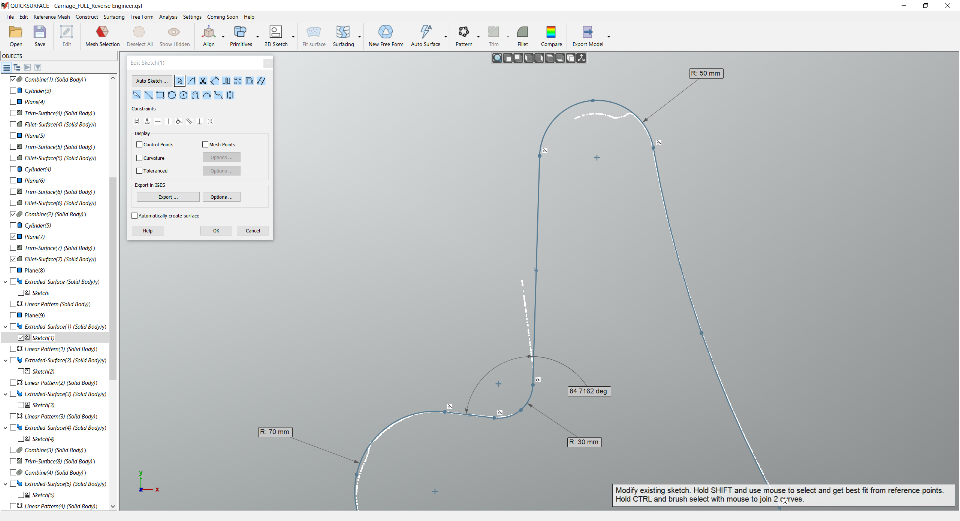
Constrained 2D Sketching
Use dimensions and constraints to create accurate sketches like in any other CAD package
3D Sketching, Loft, Sweep surfacing
Draw free form curves directly on the reference mesh then create surfaces by standard commands – loft, sweep, pipe. Join the surface or use them in trimming operations.
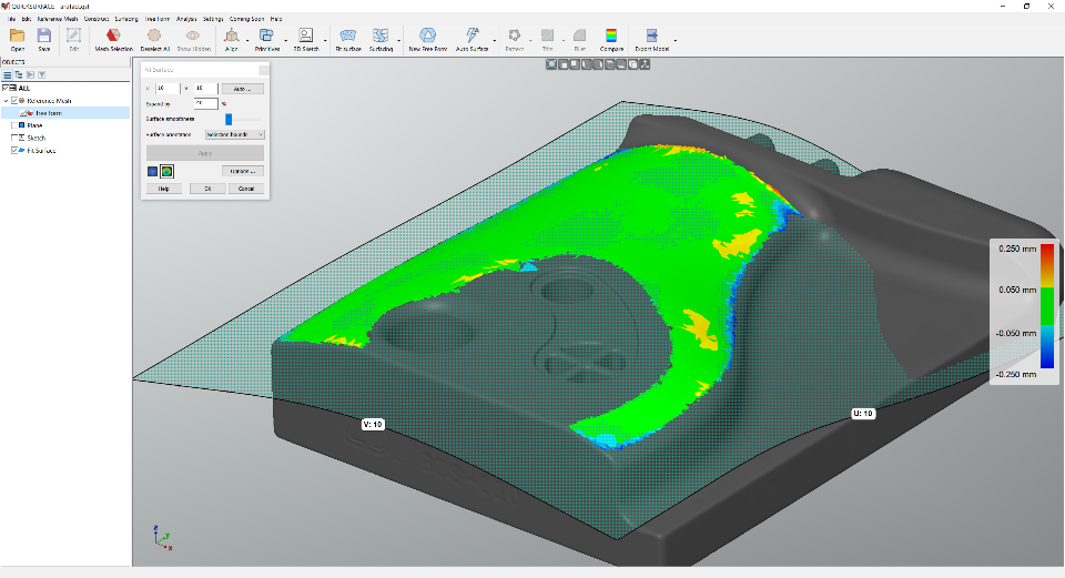
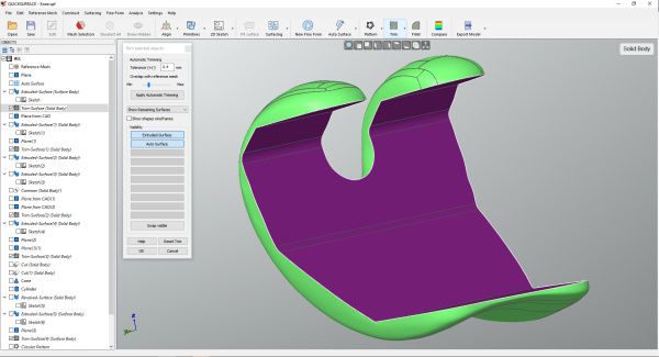
Fit Surface
Select area of interest and let the software to approximate the selection with a free form surface. The resulting surface is extended so it is suitable for trimming. The real-time deviation colour map instantly shows the quality of the surface. Automatic option allows the user to create surface as close as possible to the reference mesh.
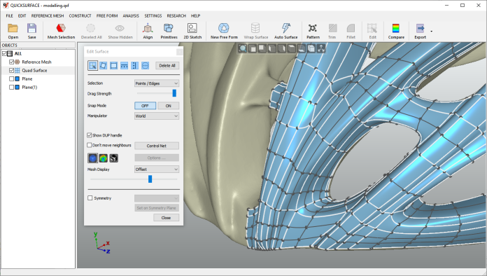
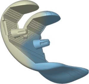
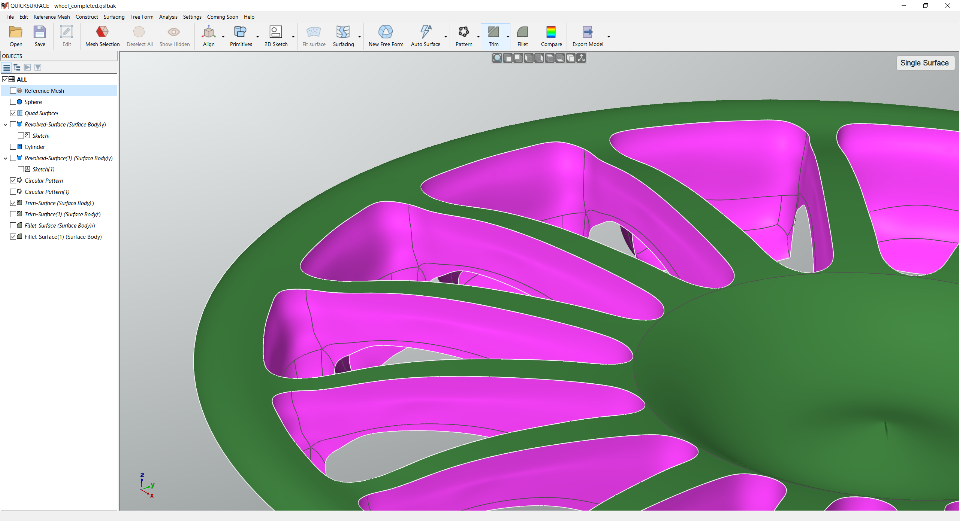
Free Form Modelling
Quad surface allows the user to reconstruct free form surface which is not possible with the standard surfacing methods.
Proprietary snap-to-mesh technology allows even non-professionals to create shapes in no time – something not available in any other solutions.
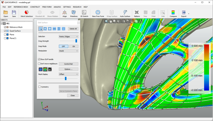
Real-time deviation analyser
Speed optimised real-time distance colour map allows the user to keep everything in control and get the most accurate results
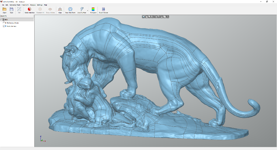
Automatic Surfacing
Create surface on organic shapes with just hit of a button.
No user interaction required.
QUICKSURFACE provides you with one of the best automatic surfacing available today. The algorithm optimises the number of resulting nurb patches to be minimal. The surface quality is G2 everywhere and G1 at extraordinary points.
Hybrid parametric modelling
Together of being parametric for the standard features, the software allows you to create CAD models as a combination of free form and prismatic features. The user can always get back and modify even the free form surfaces if needed and get the results reconstructed.
Triming & Boolean operations
Create surfaces or solids by using mutual trim operation or Boolean operations on solids. The coloured display and diagnostic tools allow you to identify the issues while performing these operations
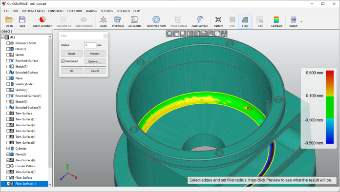
Fillet & Chamfer
The chamfer and fillet operations provide a real-time analyser. Just drag the arrow to define the fillet radius on the screen and see immediately the deviation of the fillets against the reference mesh. And all this in real-time
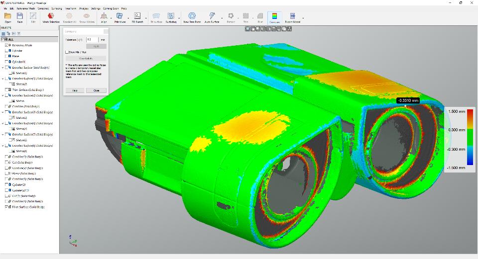
Deviation Analyser
Control the accuracy of your reconstruction with the efficient distance colour map. Compare the CAD model against the reference mesh at any time of your process
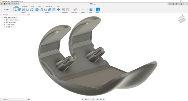
Link to other CAD Packages
Export reconstructed surfaces or solid models for use in other packages using the industry standard format STEP or IGES.
Why QUICKSURFACE?
We don’t compare our solution to other packages, but we simply highlight some of the features that make QUICKSURFACE different:
- Interactive selection by the user instead of automatic segmentation on reference mesh;
- Constrained best fit (for example the ability to constrain the direction of the cylinder to be parallel to an axis, while still getting the best fit to the points);
- Relations between extracted primitives – parallelism, perpendicularity, coincidence, offset;
- Quick alignment based on extracted primitive (datum) prioritization;
- Realtime deviation colour map in 2D Sketch mode;
- Proprietary snap-to-mesh technology for free form modelling;
- The ability to modify the automatic surface, if the design intent requires it;
- QUICKSURFACE Free Form is not only exact surfacing, the user can manually adjust the resolution and position of control points to avoid mapping of the surface to the reference mesh which may have outliers and noise;
- Realtime deviation in Free Form, helping to create lighter surfaces with less control points;
- Parametric hybrid modelling – starting with free form and basic primitives, the user can build a complex CAD model by trimming them and can later change the surfaces based on the design intent;
- Creation of watertight mesh for 3D printing by cleaning up the mesh or create boolean operations with CAD primitives – hybrid modeller;
Finally, it is in your hands – The User. Try it yourself. If you want to compare with another solution – the best would be a “speed test”, where the same part is reverse engineered in both QUICKSURFACE and another package to see the time variation. While this may be subjective, we believe the simplicity of QUICKSURFACE will make for a much faster design process on most parts.
Scan To CAD standalone products